60
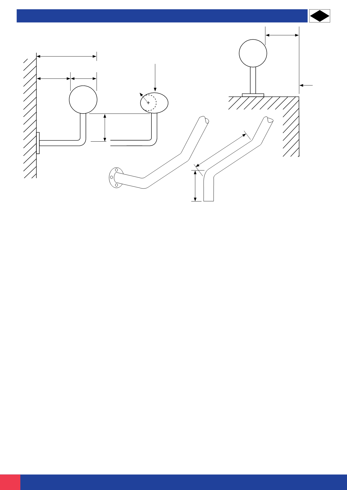
300mm (min)
Handrail end
turned down
150mm (min)
Handrail end
turned to wall
50mm (max)
Ramped or
stepped
access
Circular handrail
40 - 50mm diameter
50 - 60mm
Non-circular handrail
preferable 50mm wide x 30mm
deep with rounded edges
15mm (min)
radius
50mm (min)
(Note TGD B Method of Measurement)
Diagram 7 Handrail Design
1.1.3.6 Handrails
General guidance on handrails and guarding is given
in TGD K, but the guidance that follows applies to
handrails on accessible access routes.
Where handrails are provided on a ramped or
stepped access route:
(a)
The vertical height to the top of the upper handrail
from the pitch line of the surface of a flight should be
between 900 and 1000mm and from the surface of a
landing should be between 900 and 1100mm (refer to
Diagram 6). Where a second handrail on stairs is
provided for children or those of short stature the
vertical height to the top of a second lower handrail
from the pitch line of the surface of a flight should be
between 600 and 700mm;
(b)
Where there are two or more flights separated by
a landing or landings, the handrails should be
continuous across flights and landings, except where
broken by side access routes on landings;
(c)
Where the handrail is not continuous the handrail
should extend at least 300mm beyond the top and
bottom of a ramped approach and the top and bottom
risers of a stepped approach, and terminate in a
closed end which does not project into a route of
travel. Handrails should be terminated in such a way
that reduces the risk of clothing being caught;
(d)
The background against which the handrails are
seen should contrast visually without being highly
reflective (refer to 1.6.4);
(e)
The profile should be either circular with a
diameter of between 40 to 50mm or oval with a width
of 50mm (refer to Diagram 7);
(f)
Handrails should not protrude more than 100mm
into the surface width of the access route where this
would impinge on the stair width requirement of TGD
B – Methods of Measurement;
(g)
There should be a clearance of at least 50mm to
60mm between the handrail and any adjacent wall
surface (refer to Diagram 7);
(h)
There should be a clearance of at least 50mm
between a cranked support and the underside of the
handrail (refer to Diagram 7). The handrail support
should meet the handrail centrally on its underside.
Rationale: This will minimise the risk of the handrail
supports interrupting the smooth running of a
person’s hand along the rail;
(i)
The handrails inner face should be located no
more than 50mm beyond the surface width of the
access route (refer to Diagram 7);
(j)
Handrail fixings should be designed to meet the
loading recommendations of I.S. EN 1991-1-1:2002.
Extract from Building Regulations Part K and Part M;
HANDRAILS AND GUARDRAILS


