BLACKBURNS X-TRUDE PROFILE SYSTEM
18
BXF-50
BXF-75
BXF-100
BXF-150
BXF-200
Manufacture
Guidelines
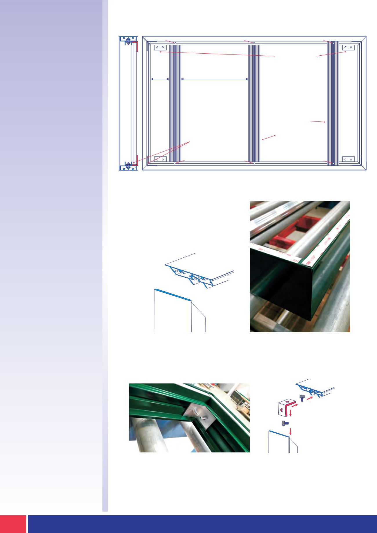
Example Frame
Construction
STAGE 1
Measure & Cut
STAGE 2
Assemble
Outer Frame
Maximum Spacing 750mm
BXF-50 / 75 / 100 / 150 /
200C Pre-cut 50/50 x 3mm
angle cleat bolted into
place using an M6 nut
bolt and washers
BXF-SFB Vertical support
rails to be rivetted to the
outer back edge
and panel joint
supports to the face
Back panel to be notched
to allow for BXF-SFB
fixing brackets if required
Max.
Spacing
350mm
BXF-50 / 75 / 100 / 150 / 200
Outer Frame Extrusion
Rivet
Rivet
Rivet
Rivet
Rivet
Rivet
BXF-50 HAS AN INTERNAL CLEAT WHICH SLIDES INTO THE SAME SLOT AS THE JOINING
STRIP, AND IS RIVETED INTO PLACE, AS THERE IS NO AVAILABILITY FOR M6 BOLT CHANNEL
IN THIS SIZE PROFILE.
When manufacturing the first requirement
is to cut the outside frame (from the profile
BXF-50/75/100/150 or 200) at a 45 degree
mitre at all four corners.
The outer frame is assembled using the matching pre-cut and drilled aluminium
angle corner brackets / cleats. They are secured into place by sliding a standard M6
hex bolt with matching nuts into the provided channel.
EXAMPLE FRAME CONSTRUCTION


