BLACKBURNS X-TRUDE COMPONENT & ASSEMBLY GUIDE
19
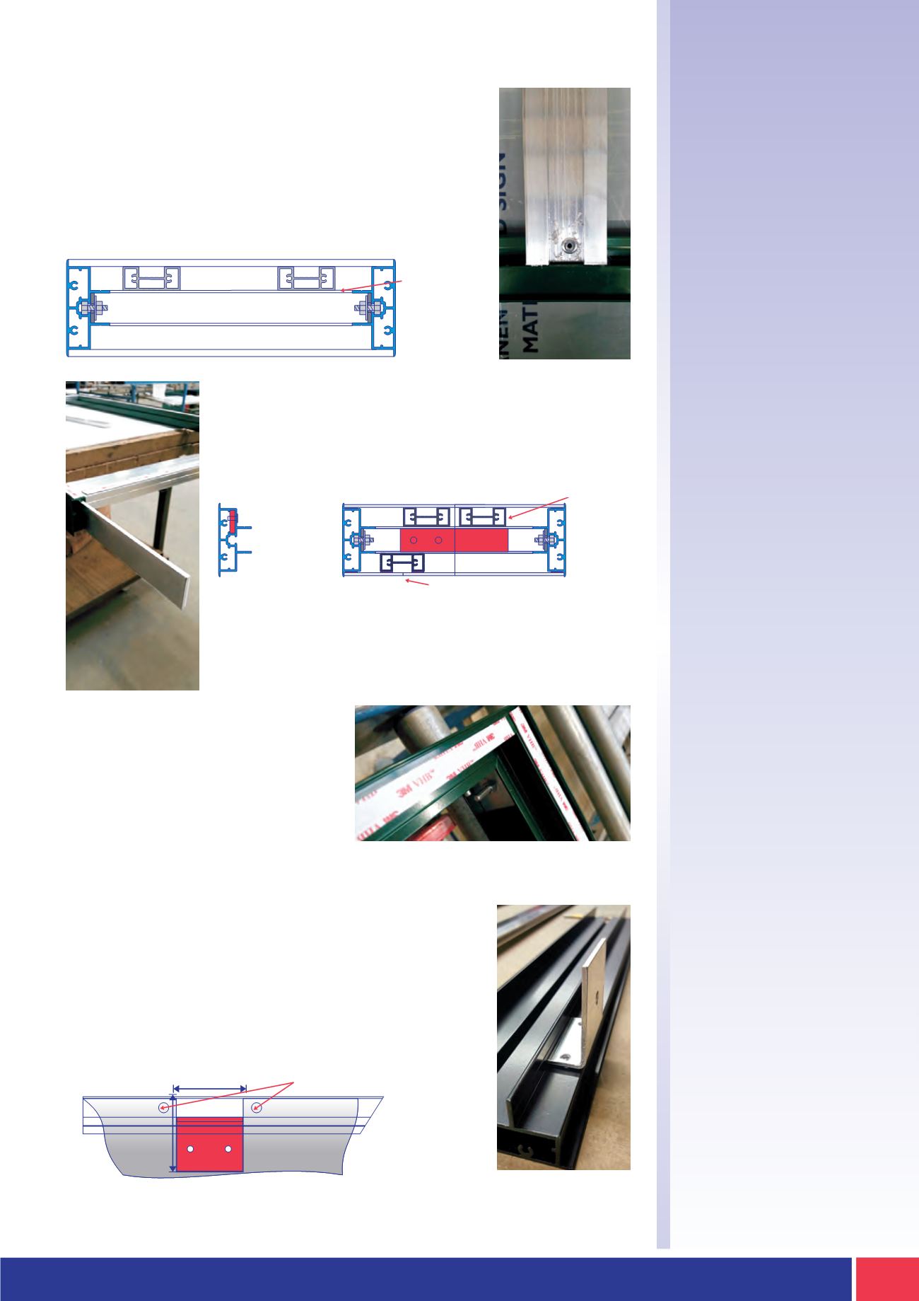
STAGE 3
Support Section
STAGE 4
Fabricating
Sections
STAGE 5
Tape Application
Hanging Brackets
(if required)
When the frame is fully fabricated it can
then be sent for painting. The frame
should then be primed and a suitable
double sided tape** applied to the
entire perimeter frame.
**
PLEASE CONSULT YOUR TAPE SUPPLIER FOR GUIDANCE ON SELECTING
THE CORRECT TAPE AND APPLICATION PROCESS
BACK PANEL IS SCREWED TO THE
FRAME TO ALLOW FOR REMOVAL
IF REQUIRED
When the outer frame is complete then introduce the BXF-SB
support brace profile. The support profile is attached along the
smallest dimension (width or height) and a minimum of two
supports are required. Additional supports are applied at a
maximum spacing of 750mm. Support sections are cut 37mm
shorter then the overall height/width and are secured in place
along the inside back edge with a rivet fixing.
When a frame is supplied in sections you introduce the
required BXF-JS 5mm aluminium joining strip. The strip slides
into the extrusion frame and is secured with a rivet into one
section only. The second side is secured on site during
installation with a self-tapping screw (if required).
An additional BXF-SB brace is also introduced to the inside
face edge staggered to the frame joint to allow a solid butt
joint in the face panel.
70
65
Back Panel
For illuminated frames the back panel is to be screwed into
place to allow for removal, and any required BXF-JS joining
strips are not secured on the second side during installation.
The back panel is also notched around the parameter where
BXF-SFB installation brackets are required. The notch site is
65mm x 70mm.
SUPPORT
SECTION TO
THE REAR OF
INNER FRAME
TO ALLOW
FOR WALL
MOUNTING
LOCATION
WITHIN
EXTRUDED
FRAME FOR
JOINING STRIP
SUPPORT
SECTION TO
THE REAR OF
INNER FRAME
TO ALLOW
FOR WALL
MOUNTING
SUPPORT SECTION TO FACE OF INNER FRAME FOR
PANEL JOINTS TO ALLOW FOR A CLEAN BUTT JOINT


